
What Is Isolation?
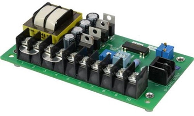
ISO202-1 Isolation Card For Use With Any ACE Motor Control
How To Vary Motor Speed With A Potentiometer
When someone wants to use a motor control to vary the speed of a motor, they typically use a potentiometer. A potentiometer is a variable resistor that is used to send a voltage range as a reference signal to the motor control. Most motor controls provide 3 connections for a potentiometer; a common, a reference, and a supply voltage. The illustration below shows how the potentiometer can be set to different positions to send any signal between 0 and 10 VDC, if using a 10 VDC supply voltage.

How To Vary Motor Speed With An Analog Signal
But what if someone doesn’t want to use a potentiometer or a knob on a panel to control the speed. What if someone wants to use another device to control the motor’s speed instead, like a PLC? Well, the potentiometer can be mimicked by sending an analog signal. In the example above, the motor control is expecting a 0-10 VDC signal, so the PLC would need to send a 0-10 VDC signal as well. However, this isn’t as easy as it seems. In the illustration below, we have a PLC with a 0-10 VDC signal, and a control expecting a 0-10 VDC signal, so they can just be connected together, right?

No. Connecting the PLC and motor control in the image above would actually cause damage to one, if not both, of the devices. Why? The drives are at different potentials. The PLC may be outputting a 0-10 VDC range, but relative to earth ground, that range might be between 14 and 24 volts. The motor control on the other hand is between 105 and 115 volts. So while the drive is expecting a 0-10 VDC like the one put out by the PLC, if you were to connect the 105 VDC potential of the motor control to the 14 VDC potential of the PLC, there would be a large rush of current which would damage components in possibly both devices.

So what’s the solution? Isolation!
What Is Isolation?
Isolation in an industrial control is a method of connecting two electrical devices of different electrical potentials without changing the electrical potential of either device, possibly preventing damage to one of those devices in the process. One method of isolation uses diodes with a transformer, (simplified in the illustration below), but is more typically done using an isolated op-amp.

Isolation Options From American Control Electronics
Some models (such as the MGC & LGP Series) always have isolation built-in by default, while others have adder cards that can be installed at the factory or in the field, like the RGA Series. Some have an isolation option that must be installed by the factory, like the PWM Series, because the isolation components are populated directly on the unit. Others yet do not have an isolation option, but isolation can still be achieved by using any of American Control Electronics stand-alone isolation cards, like the ISO202-1 and ISO101-8.